The most important step in any measurement process is setting up your measurement device correctly. Do this incorrectly and you can find out your data is useless after a measurement cycle of days or weeks. That means starting all over again—if you can.
Setting up an instrument needs focus and preparation. What do I want to know—parameters, ranges, scaling? Where am I measuring (e.g., type of network (Wye, Delta), (regulatory) limits and environment (internal, outside))? These are important questions to answer before you set up your Fluke 1748 Three-Phase Power Quality Logger.
Connecting the logger
First, set up the logger. Then start up Fluke Energy Analysis Software on your laptop, start communication with the instrument and open the instrument setup menu. You’ll see these tabs:
- Instrument
- Topology
- Measurement: Ranges and scaling
- Connection verification
- Event triggers: Set limits
- Logging: Select interval, duration and start/stop
Instrument
You have three options to set date/time, by synchronizing to:
- PC time
- Internet time
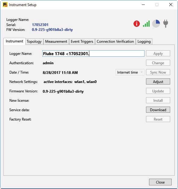
Internet time setting
PC time is a manual sync with your PC. Internet time gives more accurate timestamps for logged data but needs a constant internet connection. GPS is the most accurate real-time sync. It requires an optional GPS module, but your unit then complies with the time synchronization requirements of IEC-61000-4-30 Class A.
Topology
Topology selects the type of network (Wye or Delta).
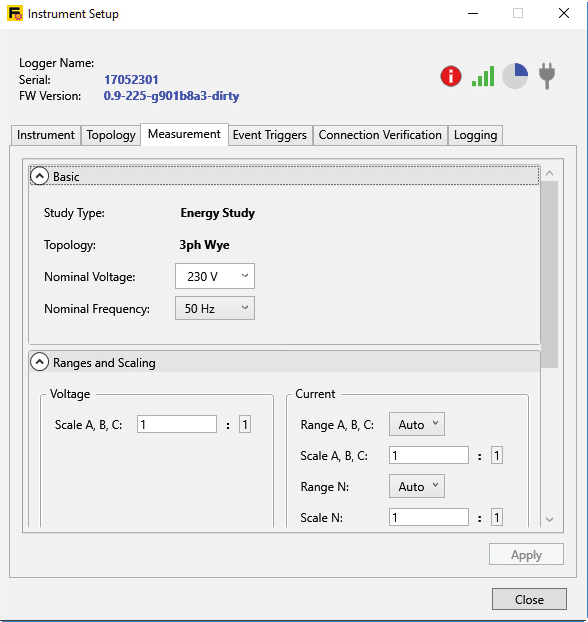
Study type and nominal voltage value selected
The unit must also know the type of study, and Fluke gives you two options. A full power quality assessment (energy study) needs both voltage and current connections. A limited setup (load study) measures current only for convenience or safety. This uses the nominal voltage values you configured in the setup, which calculate the pseudo apparent power.
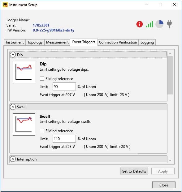
Event triggers
Event triggers basically set the limits of events like dips, swells, and interruptions to be tracked. You usually set these limits according EN 50160, but part of the dips and swells limit settings also has a checkbox called “sliding reference.”
A sliding or nominal reference voltage uses measured values filtered with a 1-minute time constant and usually only applies to medium and high voltage systems.
When the sliding reference box is not checked, the nominal voltage (the one you set up) determines the limits for dips, swells, and interruptions.
A little background
According to IEC 61000-2-8, the reference voltage for measurement purposes is either a fixed value such as the nominal or declared voltage, or a sliding value. This sliding reference is the voltage value immediately before the event (i.e., dip, swell, or interruption).
Sliding reference box not checked
The event is usually expressed in relative terms by percentage (%). It refers to the reference voltage at the point of measuring. Please note that the reference voltage for measurements on low- and medium-voltage networks is usually the nominal voltage of the network itself.


